TM 9-2320-366-34-3
16-79. M1089 FLOWMETER VALVE ASSEMBLY REPLACEMENT/ADJUSTMENT
This task covers:
a. Removal
b. Installation
c. Adjustment
d. Follow-On Maintenance
INITIAL SETUP
Equipment Conditions
Underlift lowered (TM 9-2320-366-10-2).
Batteries disconnected (TM 9-2320-366-20-3).
Hydraulic reservoir supply and return valve closed (TM
9-2320-366-10-2).
Tools/Special Tools
Tool Kit, Genl Mech (Item 78, Appendix B)
Goggles, Industrial (Item 28, Appendix B)
Tools/Special Tools (Cont)
Sling, Cargo (Item 56, Appendix B)
Materials/Parts
Nut, Self-Locking (8) (Item 211, Appendix F)
Sealing Compound (Item 75, Appendix C)
Personnel Required
(2)
NOTE
• This procedure applies to both the upper and
lower flowmeter valve assemblies. The upper
flowmeter valve assembly is shown.
• The upper flowmeter valve assembly must be
removed first.
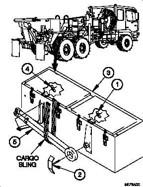
a. Removal.
(1) Remove nut (1) and bracket (2) from tool box (3).
WARNING
Tow bar weighs approximately 150 lbs (68
kgs). Attach a suitable lifting device prior to
removal. Failure to comply may result in
injury to personnel or damage to equipment.
NOTE
Steps (2) requires the aid of two assistants.
(2) Remove nut (4) and tow bar (5) from tool box (3).
16-481