TM 9-2320-366-34-4
NOTE
The value obtained in step (8) is the thickness of
the new pinion shim pack to be installed. Use as
many shims as required to equal value obtained
in step (8).
(9) If pinion cone variation number recorded in step (6) of
assembly is negative, add it to value from step (7). If
number is positive, subtract it from value from step (8).
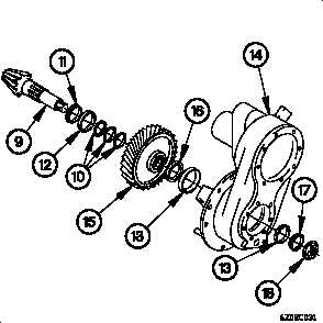
(10) Install bearing cone (11), bearing cup (12) and shim
pack (10) on pinion drive shaft (9).
(11) Install bearing cup (13) in differential carrier (14).
(12) Install pinion drive shaft (9), helical gear (15) and spacer
(16) in differential carrier (14).
(13) Install bearing cup (13) in differential carrier (14).
(14) Install bearing cone (17) on pinion drive shaft (9).
(15) Position self-locking nut (18) on pinion drive shaft (9).
NOTE
Bearing preload of the pinion assembly
must be within the following limits; new
bearings 5-45 lb-in. (0.5-5 N·m), used
bearings 10-30 lb-in. (1-3 N·m).
Perform steps (16) through (20) if torque
value is not within specifications. If torque
value is within specifications go to step
(21).
(16) Record amount of torque required to rotate pinion drive
shaft (9).
(17) Remove self-locking nut (18) on pinion drive shaft (9).
24-13