TM 9-2320-366-34-2
6-5. TRANSMISSION TURBINE SPEED SENSOR REPLACEMENT
This task covers:
a. Removal
b. Installation
c. Follow-On Maintenance
INITIAL SETUP
Equipment Conditions
Control valve module removed (para 7-10).
Tools and Special Tools
Tool Kit, Genl Mech (Item 78, Appendix B)
Wrench, Torque, 0-150 lb-in. (Item 91, Appendix
B)
Wrench Set, Socket (Item 85, Appendix B)
Tools and Special Tools (Cont)
Multimeter, Digital (Item 41, Appendix B)
Goggles, Industrial (Item 28, Appendix B)
Gloves, Rubber (Item 26, Appendix B)
Materials/Parts
Rag, Wiping (Item 60, Appendix C)
Solvent, Dry Cleaning (Item 83, Appendix C)
a. Removal.
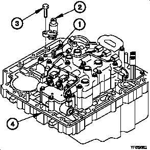
(1) Disconnect wiring harness connector (1) from turbine
speed sensor (2).
(2) Remove two screws (3) and turbine speed sensor (2)
from control valve module (4).
b. Installation.
NOTE
Handle parts carefully to prevent damage.
(1) Position turbine speed sensor (2) on control valve
module (4) with two screws (3).
(2) Tighten two screws (3) to 108-120 lb-in. (12-14 N·m).
(3) Connect wiring harness connector (1) to turbine speed sensor (2).
c. Follow-On Maintenance.
Install control valve module (para 7-10).
End of Task.
6-32