TM 9-2320-366-34-3
16-68. M1089 UNDERLIFT AND STIFFLEG ASSEMBLY REPLACEMENT
This task covers:
a. Removal
b. Installation
c. Follow-On Maintenance
INITIAL SETUP
Equipment Conditions
Underlift and stiffleg assembly unfolded and in down
position (TM 9-2320-366-10-2).
Engine shut down (TM 9-2320-366-10-1).
Rear tool box removed (TM 9-2320-366-20-4).
Hydraulic reservoir supply and return valves closed
(TM 9-2320-366-10-2).
Rear ladder removed (TM 9-2320-366-20-4).
Tools and Special Tools
Wrench, Torque, 0-600 lb-ft (Item 97, Appendix B)
Goggles, Industrial (Item 28, Appendix B)
Wrench Set, Socket (Item 84, Appendix B)
Sling, Cargo (Item 56, Appendix B)
Tool Kit, Genl Mech (Item 78, Appendix B)
Pan, Drain (Item 43, Appendix B)
Tools and Special Tools (Cont)
Wrench, Torque, 0-175 lb-ft (Item 92, Appendix
B)
Wrench Set, Crowfoot, Ratcheting (TM 9-2320-
366-20)
Materials/Parts
Cap and Plug Set (Item 17, Appendix C)
Shackle (2) (Item 80, Appendix C)
Dispenser, Pressure Sensitive Adhesive Tape
(Item 30, Appendix C)
Nut, Self-locking (20) (Item 179, Appendix F)
Nut, Self-locking (2) (Item 176, Appendix F)
Lockwasher (4) (Item 130, Appendix F)
Pin, Cotter (2) (Item 327, Appendix F)
Nut, Self-locking (24) (Item 211, Appendix F)
Personnel Required
(3)
a. Removal.
CAUTION
Cap or plug hydraulic hoses to prevent
contamination of hydraulic system. Failure to
comply may result in damage to equipment.
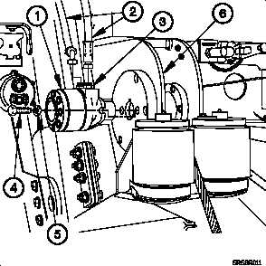
NOTE
· Left and right pay-out hydraulic motors are
removed the same way. Left side shown.
· Tag hydraulic hoses and connection points prior
to disconnecting.
(1) Position drain pan under pay-out hydraulic motor (1).
(2) Disconnect two hoses (2) from fittings (3).
(3) Remove two bolts (4), washers (5), and pay-out
hydraulic motor (1) from spooler weldment (6).
(4) Perform steps (1) through (3) on right side pay-out
hydraulic motor (1).
16-408