TM 9-2320-366-34-1
Change 1 2-413
RESISTANCE TEST
CAUTION
NOTE
Use care when testing electrical connectors.
Do not damage connector pins or sockets
with multimeter probes. Failure to comply
may result in damage to equipment.
Inspect connector pins/sockets for damage,
corrosion, and serviceability. Check that
connector pins are not pushed back and
are capable of making good contact.
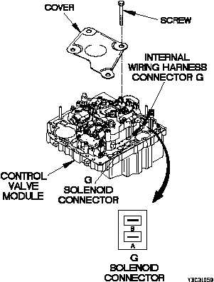
(1) Set multimeter to ohms.
(2) Connect positive (+) probe of multimeter
to G solenoid connector pin A.
(3) Connect negative (-) probe of multimeter
to G solenoid connector pin B and note
reading on multimeter.
(4) If resistance is less than 2.5 ohms or
greater than 5.0 ohms, replace
G solenoid (para 7-11).
(5) If resistance is between 2.5-5.0 ohms,
replace WTEC II TEPSS (TM 9-2320-366-
20-4).
(6) Connect internal wiring harness
connector G to G solenoid connector.
(7) Install cover on control valve module with
four screws.
(8) Install control valve module (para 7-10).
(9) Connect batteries (TM 9-2320-366-20-3).