TM 9-2320-366-34-1
2-27
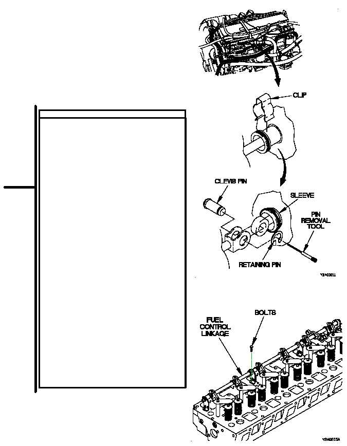
FUEL CONTROL LINKAGE TEST
(1) Raise cab (TM 9-2320-366-10-1).
(2) Remove valve cover (TM 9-2320-366-20-3).
(3) Remove rocker arms (para 3-12).
(4) Remove clip from fuel control linkage.
(5) Slide sleeve, using soft jawed pliers, into
cylinder head.
(6) Remove retaining ring and clevis pin, using
pin removal tool.
(7) Check fuel control linkage for smooth
operation.
(8) If fuel control linkage still appears to be
binding, remove fuel injectors (para 4-2).
(9) With fuel injectors compressed, check fuel
injector racks for smooth operation.
(10) If fuel injector racks are sticky, fuel injector
is faulty.
(11) Check fuel control linkage for smooth
operation.
(12) If still binding, loosen four bolts holding fuel
control linkage to cylinder head.
(13) Operate fuel control linkage by hand.
(14) Tighten two outer bolts in fuel control
linkage to 30 lb-in. (3.5 N·m).
(15) Tighten two inner bolts in fuel control
linkage to 30 lb-in. (3.5 N·m). If fuel
control linkage is still binding, replace
fuel control linkage (para 4-7).
(16) Install fuel injectors (para 4-2).
(17) Install clevis pin and retaining ring using pin
insertion tool.
(18) Slide sleeve out of cylinder head and install
clip.
(19) Install rocker arms (para 3-12).
(20) Install valve cover (TM 9-2320-366-20-3).
(21) Lower cab (TM 9-2320-366-10-1).


