Change 1 2-211
TM 9-2320-366-34-1
WARNING
Wear appropriate eye protection when working
under vehicle due to the possibility of falling
debris. Failure to comply may result in injury
to personnel.
Ensure exhaust system is cool before
performing troubleshooting. Failure to comply
may result in injury to personnel.
CAUTION
Loose or dirty connectors may cause
intermittent loss of power to transmission
ECU and diagnostic codes to be logged.
Ensure that all connectors are clean and tight
before performing troubleshooting. Failure to
comply may result in incorrect test results.
Use care when testing electrical connectors.
Do not damage connector pins or sockets
with multimeter probes. Failure to comply
may result in damage to equipment.
NOTE
Inspect connector pins/sockets for damage,
corrosion, and serviceability. Check that
connector pins are not pushed back and
are capable of making good contact.
CONTINUITY TEST
(12) Connect negative (-) probe of multimeter
to ground and note reading on multimeter.
(13) If continuity is present, transmission
external wiring harness is shorted; replace
transmission external wiring harness
(para 6-7).
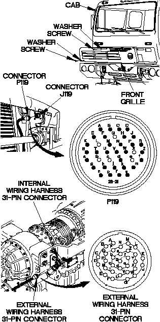
(1) Remove two screws and washers from
front grille.
(2) Remove screw and washer from front
grille.
(3) Remove front grille from cab.
(4) Disconnect connector P119 from
connector J119.
(5) Disconnect external wiring harness 31-pin
from internal wiring harness 31-pin
connector.
(6) Set multimeter to ohms.
(7) Connect positive (+) probe of multimeter
to connector P119-T.
(8) Connect negative (-) probe of multimeter to
external wiring harness 31-pin connector
pin J and note reading on multimeter.
(9) If continuity is not present, replace
transmission external wiring harness
(para 6-7).
(10) Connect positive (+) probe of multimeter
to connector P119-T.
(11) Connect negative (-) probe of multimeter
to all other pins in connector P119 and
note reading on multimeter.
CONTINUITY TEST